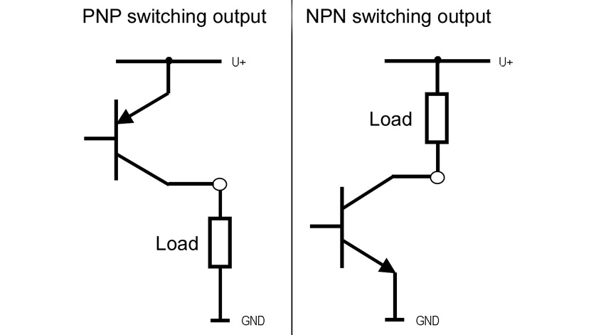
Manufacturers of electronic pressure switches often offer both PNP and NPN switching outputs. Here is a brief explanation how the two different outputs should be connected.
In principle, both are bipolar transistors in which only the internal arrangement of the pn transitions differs. This is why the load must be connected differently to the transistor outputs.
PNP switching output
The load is connected to the switching output with GND as the reference point. When a change in signal takes place by reaching a pressure value, the supply voltage (U+) is “switched through”, allowing current to flow from U+ through the transistor and through the load to GND.
NPN switching output
The load is connected to the switching output with U+ as the reference point. When a change in signal takes place by reaching a pressure value, the supply voltage (U+) is “switched on”, allowing current to flow from U+ through the load via the transistor and to GND.
Fields of application
In my experience, PNP switching outputs are used mainly in Europe, and NPN outputs almost exclusively in Asia. In contrast, in North America, the country where the transistor was invented, relay outputs with potential-free contacts for AC 110 V loads are most widely used.
Note
The WIKA pressure switch PSD-30 is available either with PNP or NPN switching output.