When we’re talking communication protocols, a UART, SPI and I2C are the common hardware interfaces people use in microcontroller development.
This article will compare the various interfaces: UART, SPI and I2C and their differences. We will be comparing them with various factors through their protocols, advantages and disadvantages of each interface, etc and we will be providing some examples of how these interfaces are being used in microcontrollers.
UART Interface
What is UART?
- Stands for Universal Asynchronous Reception and Transmission (UART)
- A simple serial communication protocol that allows the host communicates with the auxiliary device.
- UART supports bi-directional, asynchronous and serial data transmission.
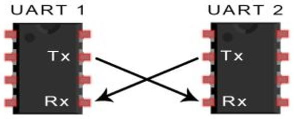
- It has two data lines, one to transmit (TX) and another to receive (RX), which are used to communicate through digital pin 0, digital pin 1.
- TX and RX are connected between two devices. (eg. USB and computer)
- UART can also handle synchronization management issues between computers and external serial devices.
How does it work?
- It can operate between devices in 3 ways:
- Simplex = data transmission in one direction
- Half-duplex = data transmission in either direction but not simultaneously
- Full-duplex = data transmission in both directions simultaneously
- Once connected, data flows from TX of the transmitting UART to RX of the receiving UART.
- As UART is an asynchronous serial transmission protocol = No clocks
- Transmitting UART converts parallel data from the master device (eg. CPU) into serial form and transmit in serial to receiving UART. It will then convert the serial data back into parallel data for the receiving device
- As UART has no clocks, UART adds start and stop bits that are being transferred to represent the start and end of a message.
- This helps the receiving UART know when to start and stop reading bits. When the receiving UART detects a start bit, it will read the bits at the defined BAUD rate.
- UART data transmission speed is referred to as BAUD Rate and is set to 115,200 by default (BAUD rate is based on symbol transmission rate, but is similar to bit rate).
- Both UARTs must operate at about the same baud rate. If the difference of BAUD rate is more than 10%, the timing of bits may be off and render the data unusable. The user must ensure UARTs are configured to transmit and receive from the same data packet.
UART Working Protocol
- A UART that is transmitting data will first receive data from a data bus that is sent by another component (eg. CPU).
- After getting the data from the data bus, it will add a start bit, a parity bit, and a stop bit to create the data packet.
- The data packet is then transmitted at the TX pin where the receiving UART will read the data packet at its RX pin. Data is sent until there is no data left in the transmitting UART.
Data Transmission and Receiving
- Once data is being transmitted by the transmit FIFO, the FIFO ‘BUSY’ flag will be asserted and active during the process.
- FIFO = First in, First out. It’s a UART buffer that that forces each byte to be passed in sequence to the receiving UART.
- The ‘BUSY’ bit will only be inactive after data is finished transmitting, the FIFO is emptied and every bit has been transmitted including the stop bit.
- When the UART receiver is idle and if the data input is low after start bit is received, the receive counter will start running and expect to receive data in the 8th cycle of BAUD16.
- If RX is still low during the 8th cycle of Baud16 while the start bit is valid, it would be processed as the wrong start bit and thus ignored.
- If the start bit is valid, data bits are sampled every 16th cycle of Baud16 based on the length of the data character. If the parity mode is enabled, the parity bit is also detected.
- If RX is high, a valid stop bit will be acknowledged. Otherwise, a framing error will occur.
- When a complete data packet is received, the data is stored in the receiving FIFO.
Interrupt Control
- The goal of interrupts is to send the content of a buffer automatically.
- User can use interrupts in the event of:
- FIFO Overflow Error
- Line-break error (RX signal remains 0 including the check and the stop bit.)
- Parity error
- Frame error (Stop bit not 1)
- Receiving timeout (receiving FIFO has data but not full and subsequent data does not transmit)
- Transmitting
- Receiving
FIFO Operation
- UART module of the Stellaris family of ARM CPUs contain two 16-byte FIFOs: one for transmission and one for the reception.
- They can be configured to trigger interrupts at various depths. For example, 1/8, 1/4, 1/2, 3/4, and 7/8 depth.
- If the receiving FIFO triggers an interrupt at 1/4, a receive interrupt is triggered when the UART receives 4 data.
Working process of transmitting FIFO:
- The process is initiated as soon as data is entered. The transmission is time-consuming, thus, other data that needs to be sent can continue to enter the transmitting FIFO.
- When the transmitting FIFO is full, the user will have to wait, or you will lose your data.
- The transmitting FIFO will send the data bit by bit until the transmitting FIFO is completely empty. After transmitted data is clear, an extra slot will be added in the transmitting FIFO.
Working process of receiving FIFO:
- When the hardware receives the data, it will be stored into the receiving FIFO. The program will retrieve and erase the data automatically from the receiving FIFO, so there will be space in the receiving FIFO. If the data in the receiving FIFO is not erased and the receiving FIFO is full, the data will be lost.
- The transceiver FIFO is to solve the issue regarding the CPU being inefficient and the UART transceiver being interrupted too frequently. Using UART communication, the interrupt mode is simpler and more efficient than the polling method. With no transceiver FIFO, each data will be interrupted once and become inefficient. With a transceiver FIFO, it can generate an interrupt and constantly transmit and receive data (up to 14), which improves the transmission and reception efficiency.
- Data loss would not occur as a result of the FIFO as it has already foreseen any problems in the process of sending and receiving. As long as the UART is initialized, the interrupt routine will do everything automatically.
Loopback
- UART has an internal loopback function for diagnostics or debugging where data is sent from TX will be received by the RX input.
Serial Infrared Protocol
- UART has an IrDA Serial Infrared (SIR) encoder/decoder module. The IrDA SIR module translates between an asynchronous UART data stream and a half-duplex serial SIR interface.
- It is used to provide a digital coded output and a decoded input to the UART. The UART signal pin can be connected to an infrared transceiver for the IrDA SIR physical layer connection.
Advantages of Using UART
- Simple to operate, well documented as it is a widely used method with a lot of resources online
- No clock needed
- Parity bit to allow for error checking
Disadvantages of Using UART
- Size of the data frame is limited to only 9 bits
- Cannot use multiple master systems and slaves
- Baud rates of each UART must be within 10% of each other to prevent data loss.
- Low data transmission speeds
Examples of UART in Microcontrollers:
USB CP2102 Serial Converter
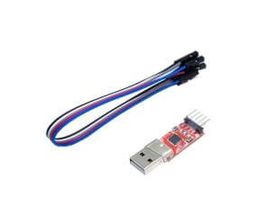
- Highly-integrated USB to UART bridge controller providing a simple solution for updating RS-232 designs to USB using minimum components and PCB space. It provides USB connectivity to devices with a UART interface.
- It uses a standard USB type A male and TTL 6pin connector
- This USB CP2102 Serial Converter is a small adapter for Arduino/Seeeduino board to accept firmware upgrades from a computer.
FT232r USB UART / USB to UART 5V
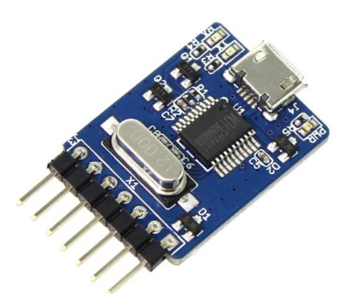
- Seeed offers a similar product: USB to UART 5V
- This is a USB to serial UART interface which simplifies USB to serial designs.
- Reduces external component count while operating efficiently with a USB host controller using as little as possible of the total USB bandwidth available.
- For the USB to UART 5V, it is based on CH340 which is a USB bus convert chip and it can realize USB convert to a serial interface.
- This USB will convert to IrDA infrared or USB convert to printer interface and can also be used for uploading code or communicating with MCUs.
UART Seeeduino V4.2
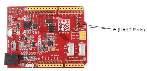
- All Arduino boards have at least one serial port (UART) which communicates on digital pins 0 (RX) and 1 (TX) as well with the computer via USB.
- This is an Arduino-compatible board, which is based on ATmga328P MCU. With an ATMEGA16U2 as a UART-to-USB converter, the board can basically work like an FTDI chip and it can be programmed via a micro-USB cable.
Base Shield V2
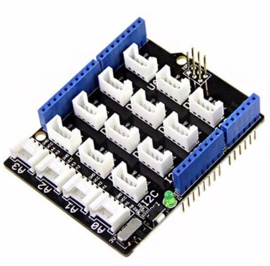
- Arduino Uno is the most popular Arduino board so far, however, it is sometimes frustrating when your project requires a lot of sensors or LEDs and your jumper wires are in a mess.
- The purpose of this product is to help you get rid of the breadboard and jump wires. With the rich grove connectors on the baseboard, you can add all the grove modules to the Arduino Uno very conveniently!
- These devices can be connected via UART and I2C (the next communication peripheral which I am going to touch on!)
I2C Interface
What is I2C?
- Stands for Inter-integrated-circuit (I2C)
- It is a serial communications protocol similarly to UART. However, it is not used for PC-device communication but instead with modules and sensors.
- It is a simple, bidirectional two-wire synchronous serial bus and requires only two wires to transmit information between devices connected to the bus.
- They are useful for projects that require many different parts (eg. sensors, pin, expansions and drivers) working together as they can connect up to 128 devices to the mainboard while maintaining a clear communication pathway!
- This is because I2C uses an address system and a shared bus = many different devices can be connected using the same wires and all data are transmitted on a single wire and have a low pin count. However, the tradeoff for this simplified wiring is that it is slower than SPI.
- Speed of I2C is also dependent by data speed, wire quality and external noise
- The I2C protocol is also used as a two-wire interface to connect low-speed devices like microcontrollers, EEPROMs, A/D and D/A converters, I/O interfaces and other similar peripherals in embedded systems.
How does it work?
- It has 2 Lines which are SCL (serial clock line) and SDA (serial data line acceptance port)
- CL is the clock line for synchronizing transmission. SDA is the data line through which bits of data are sent or received.
- The master device initiates the bus transfer of data and generates a clock to open the transferred device and any addressed device is considered a slave device.
- The relationship between master and slave devices, transmitting and receiving on the bus is not constant. It depends on the direction of data transfer at the time.
- If the master wants to send data to the slave, the master must first address the slave before sending any data.
- The master will then terminate the data transfer. If the master wants to receive data from the slave, the master must again address the slave first.
- The host then receives the data sent by the slave and finally, the receiver terminates the receiving process. The host is also responsible for generating the timing clock and terminating the data transfer.
- It is also necessary to connect the power supply through a pull-up resistor. When the bus is idle, both lines operate on a high power level.
- The capacitance in the line will affect the bus transmission speed. As the current power on the bus is small, when the capacitance is too large, it may cause transmission errors. Thus, its load capacity must be 400pF, so the allowable length of the bus and the number of connected devices can be estimated.
I2C Working Protocol
Data Transmission Method
- The master sends the transmitting signal to every connected slave by switching the SDA line from a high voltage level to a low voltage level and SCL line from high to low after switching the SDA line.
- The master sends each slave the 7 or 10-bit address of the slave and a read/write bit to the slave it wants to communicate with.
- The slave will then compare the address with its own. If the address matches, the slave returns an ACK bit which switches the SDA line low for one bit. If the address does not match its address, the slave leaves the SDA line high
- The master will then send or receive the data frame. After each data frame has been transferred, the receiving device returns another ACK bit to the sender to acknowledge successful transmission.
- To stop the data transmission, the master sends a stop signal to the slave by switching SCL high before switching SDA high
Clock Synchronisation
- All masters generate their own clocks on the SCL line to transmit messages on the I2C bus.
- Data is only valid during the high period of the clock.
- Clock synchronization is performed by connecting the I2C interface to the SCL line where the switch goes from high to low. Once the device’s clock goes low, it keeps the SCL line in this state until it reaches the high level of the clock.
- If another clock is still in a low period, the low-to-high switch does not change the state of the SCL line. The SCL line is always held low by the device with the longest low period. At this time, the device with a short and low period will enter a high and waiting state.
- When all relevant devices have completed their low period, the clock line goes high.
- After that, there is no difference in the state of the device clock and the SCL line, and all devices begin to count their high period. The device that first completes the high period will pull the SCL line low again.
- The low period of the synchronous SCL clock is determined by the device with the longest low clock period, while the high period is determined by the device with the shortest high clock period.
Transmission Modes
Quick Mode:
- Fast mode devices can receive and transmit at 400kbit/s. They have to be able to synchronize with a 400kbit/s transmission and extend the low period of the SCL signal to slow down the transmission.
- Fast mode devices are backwards compatible and can communicate with standard mode devices from 0 to 100 kbit/s I2C bus systems. However, as standard mode devices are not upward compatible, they cannot operate in a fast I2C bus system. The fast mode I2C bus specification has the following characteristics compared to the standard mode:
- The maximum bit rate is increased to 400 kbit/s;
- Adjusted the timing of the serial data (SDA) and serial clock (SCL) signals.
- Has the function of suppressing glitch and the SDA and SCL inputs have Schmitt triggers.
- The output buffer has a slope control function for the falling edges of the SDA and SCL signals
- Once the power supply of the fast mode device is turned off, the I/O pins of SDA and SCL must be left idle and cannot block the bus.
- The external pull-up device connected to the bus must be tuned to accommodate the shortest maximum allowable rise time of the fast mode I2C bus. For buses with a maximum load of 200pF, the pull-up device of each bus can be a resistor. For a bus with a load between 200pF and 400pF, the pull-up device can be a current source (maximum 3mA) or a switched resistor circuit.
High-Speed Mode:
- Hs mode devices can transmit information at bit rates up to 3.4 Mbit/s and remain fully backwards compatible with fast mode or standard mode (F/S mode) devices that can communicate bi-directionally in a speed mixed bus system.
- The Hs mode transmission has the same serial bus principle and data format as the F/S mode system except for arbitration and clock synchronization which is not performed.
- The I2C bus specification in high-speed mode is as follows:
- In high speed (Hs) mode, the master device has an open-drain output buffer for the high-speed (SDAH) signal and an open-drain pull-down and current source pull-up circuit at the high-speed serial clock (SCLH) output. This shortens the rise time of the SCLH signal and at any time, only one host current source is active;
- In the Hs mode of a multi-master system, arbitration and clock synchronization are not performed in order to speed up the bit processing capability. The arbitration process normally ends after the host code is transmitted in the F/S mode.
- The Hs mode master device generates a high and low serial clock signal with a ratio of 1:2 which removes the timing requirements for setup and hold time.
- The Hs mode device can have a built-in bridge. During Hs mode transmission, the SDAH and SCLH lines of the Hs mode device are separated from the SDA and SCL lines which reduces the capacitive loading of the SDAH and SCLH lines and make rise and fall faster.
- The difference between Hs mode slave devices and F/S slave devices is the speed at which they operate.
- The Hs mode device can suppress glitches, and the SDAH and SCLH outputs also have a Schmitt trigger;
- The output buffer of the Hs mode device has a slope control function for the falling edges of the SDAH and SCLH signals.
Advantages of using I2C
- Has a low pin/signal count even with numerous devices on the bus
- Flexible, as it supports multi-master and multi slave communication.
- Simple as it only uses 2 bidirectional wires to establish communication among multiple devices.
- Adaptable as it can adapt to the needs of various slave devices.
- Support multiple masters.
Disadvantages of using I2C
- Slower speed as it requires pull-up resistors rather than push-pull resistors used by SPI. It also has an open-drain design = limited speed.
- Requires more space as the resistors consume valuable PCB real estate.
- May become complex as the number of devices increases.
Examples of I2C in Microcontrollers
Grove – I2C Hub (6 Port)
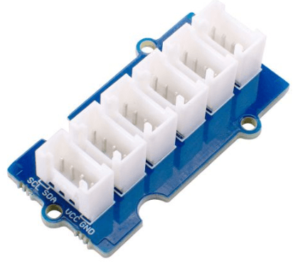
- I2C is a very popular communication protocol. In the Grove system, I2C is used by 80+ sensors for communication, 19 of which are related to environmental monitoring.
- Today more and more MCUs uses 3.3V communication levels, but the traditional ArduinoUno still uses 5V, which leads to many modules, especially sensor modules, needing to be levelled when using them.
- We actually worked on this area, and now most of the Grove sensor modules have a level shifting function, and users do not need to consider the use of 3.3V or 5V MCU when using it. This is in line with Grove’s motto; plugin, and use it, it’s that simple. For a more detailed sensor review compatibility, you can view our Grove Selection Guide.
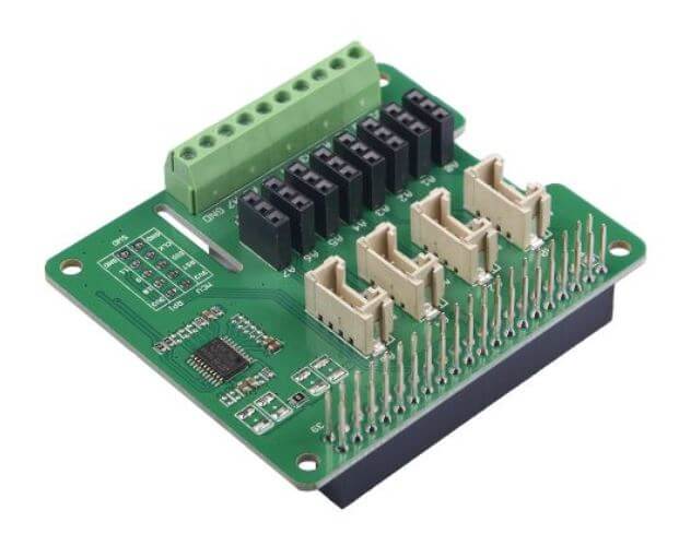
4-Channel 16-Bit ADC for Raspberry Pi (ADS1115)
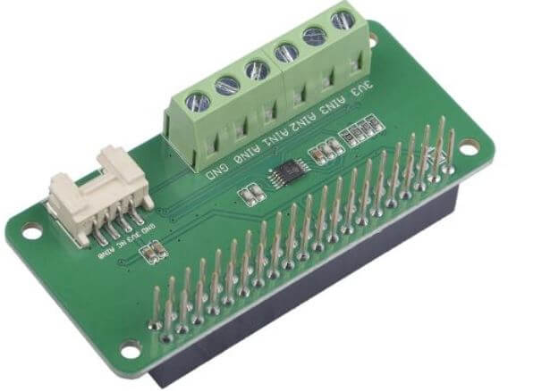
- This product by Seeed is fully compatible with Raspberry Pi.
- It is used for a Raspberry Pi without an analog-to-digital converter, or when you need a more accurate ADC.
- We provide 4-channel 16-bit ADC for Raspberry Pi (ADS1115) over I2C, a 4-channel ADC based on Texas Instrument ADS1115, which is a high-precision, low-power, 16-bit ADC chip.
I2C Arduino
- I2C communication can also be used between two Arduino boards
- Used only for short-distance communication and uses a synchronised clock pulse.
- Mainly used to communicate with sensors or other devices which have to send information to a master.
I2C Driver/Adapter-Easily Driver I2C Devices
- I²C Driver is an easy-to-use, open-source tool for controlling I²C devices. It works with Windows, Mac, and Linux, and has a built-in colour screen that shows a live “dashboard” of all the I²C activity.
- With the built-in display shows a heatmap of all active network nodes, you are able to observe from an I²C network with multiple devices which ones are the most active.
- When an I²C Driver is connected to an existing I²C bus, it “snoops” the traffic and displays it on the screen.
- This provides an excellent tool for debugging I²C issues because you can listen in on the conversation as it happens.
MCP 23017
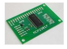
- 16-bit, general-purpose parallel I/O expansion for the I2C bus. Similar to MCP23S17 except for serial interface (I2C vs SPI).
- Port expander that gives the user virtually identical ports compared to standard microcontrollers.
PCF 8574
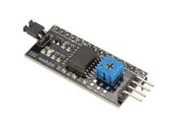
- Provides general-purpose remote I/O expansion via the two-wire bidirectional I2C-bus (serial clock (SCL), Serial Data (SDA)).
- Seeed will be using this in our future products, do keep a lookout!
Grove Base Hat for Raspberry Pi
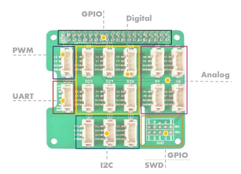
- What is Grove?
- It is a modular, standardized connector prototyping system. Grove takes a building block approach to assemble electronics. which makes it easier to connect, experiment and build and simplifies the learning system.
- Today, the grove series of sensors, actuators, and displays have grown into a large family and today we introduce the Raspberry Pi to the whole Grove System.
- The Grove Base Hat for Raspberry Pi provides Digital/Analog/ I2C/ PWM/UART port to meet all your needs.
- With the help of the build-in MCU, a 12-bit 8 channel ADC is also available for Raspberry Pi. Currently, more than 60 groves have supported the Grove Base Hat for Raspberry Pi.
SPI Interface
What is SPI?
- Stands for Serial Peripheral Interface (SPI)
- It is similar to I2C and it is a different form of serial-communications protocol specially designed for microcontrollers to connect.
- Operates at full-duplex where data can be sent and received simultaneously.
- Operate at faster data transmission rates = 8Mbits or more
- It is typically faster than I2C due to the simple protocol. Even if data/clock lines are shared between devices, each device will require a unique address wire.
- Used in places where speed is important. (eg. SD cards, display modules or when info updates and changes quickly like thermometers)
How does it work?
- Communicate with 2 ways:
- Selecting each device with a Chip Select line. A separate Chip Select line is required for each device. This is the most common way RPi’s currently use SPI.
- Daisy chaining where each device is connected to the other through its data out to the data in line of the next.
- There is no limit to the number of SPI device that can be connected. However, there are practical limits due to the number of hardware select lines available on the main device with the chip select method or the complexity of passing data through devices in the daisy-chaining method.
- In point-to-point communication, the SPI interface does not require addressing operations and is full-duplex communication, which is simple and efficient.
SPI Working Protocol
- The SPI communicates via 4 ports which are:
- MOSI – Master Data Output, Slave Data Input
- MISO – master data input, slave data output
- SCLK – clock signal, generated by the master device, up to fPCLK/2, slave mode frequency up to fCPU/2
- NSS – Slave enabled signal, controlled by the master device, some ICs will be labelled as CS (Chip select)
- In a multi-slave system, each slave requires a separate enable signal, which is slightly more complicated on hardware than the I2C system.
- The SPI interface is actually two simple shift registers in the internal hardware. The transmitted data is 8 bits. It is transmitted bit by bit under the slave enable signal and shift pulse generated by the master device. The high bit is in the front and the low bit is in the back.
- The SPI interface is synchronous serial data transmission between the CPU and the peripheral low-speed device. Under the shift pulse of the master device, the data is transmitted bit by bit. The high bit is in the front and the low bit is in the back. It is full-duplex communication, and the data transmission speed is overall faster than the I2C bus and can reach speeds of a few Mbps.
Advantages of using SPI
- The protocol is simple as there is no complicated slave addressing system like I2C.
- It is the fastest protocol compared to UART and I2C.
- No start and stop bits unlike UART which means data can be transmitted continuously without interruption
- Separate MISO and MOSI lines which means data can be transmitted and received at the same time
Disadvantages of using SPI
- More Pin ports are occupied, the practical limit to a number of devices.
- There is no flow control specified, and no acknowledgement mechanism confirms whether data is received unlike I2C
- Uses four lines – MOSI, MISO, NCLK, NSS
- No form of error check unlike in UART (using parity bit)
- Only 1 master
Examples of SPI in Microcontrollers:
MCP 3008 / Grove I2C ADC
- Seeed does offer a similar product which has the same functions: Grove I2C ADC but its communication peripheral is I2C.
- It is 10 bit 8-channel analogue-to-digital converter (ADC).
- For the MCP 3008, it connects to the Raspberry Pi using an SPI serial connection. Done by using the hardware SPI bus or any four GPIO pins and software SPI to connect to the MCP 3008.
Serial CAN-BUS Module based on MCP2551 and MCP2515
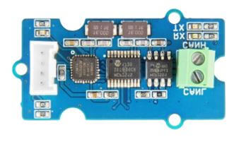
- This Seeed product: Serial CAN Bus module provides your Arduino with CAN bus capabilities and allows you to hack your vehicle. It lets you read and write messages to the CAN bus.
- CAN bus is a messaging protocol system that lets various microcontrollers and sensors within a vehicle to talk to each other. CAN provides long-distance, medium communication speed, and high reliability.
- This Serial CAN Bus module can also be connected to your Arduino through the on-board Grove connector.
- Interfaces with microcontrollers via SPI.
SPI Seeeduino V4.2
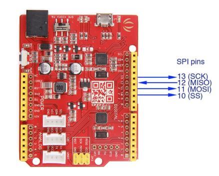
- SPI serial communication can be used with Arduino for communication between two Arduinos where one Arduino will act as master and another one will act as a slave.
- Used to communicate over short distances at high speed.
- This is the same product: Arduino v4.2 from the above UART example
ENC28J60 OVERLAYS HAT for Raspberry pi
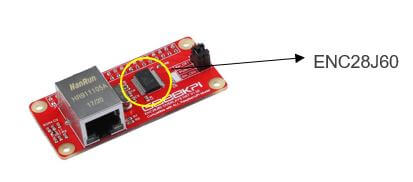
- The Pi zero ENC28J60 is a simple Network Adapter module for Pi zero that is very easy to assemble and configure.
- It allows your Raspberry Pi zero to access the network smoothly, and it is easy to do system updates and software installation operations.
- Microchip’s ENC28J60 is a 28-pin, 10BASE-T stand-alone Ethernet controller with an SPI interface.
- The SPI interface serves as a communication channel between the host controller and the ENC28J60.
SPI Driver/Adapter-Easily Driver SPI Devices
- This is a similar product as the I2C Driver/Adapter-Easily Driver I2C Device but for SPI instead. It is an easy-to-use tool for controlling SPI devices. It works with Windows, Mac, and Linux, and has a built-in colour screen that shows a live logic-analyzer display of all SPI traffic.
- Similarly, it uses a standard FTDI USB serial chip to talk to the PC, so no special drivers need to be installed. The board includes 3.3 and 5 V supplies with voltage and current monitoring.
- SPI flash is very common, and by using a test clip, SPIDriver makes it convenient to read and write SPI flash in-circuit. A short script is all it takes to read or write an Atmel’s flash and SPI LED strips are also easy to hook up to the SPI Driver, You can also be able to control them directly which makes them much more fun!
- Using SPI in this secnario is fast enough to smoothly animate long strips and achieve POV effects. Short strips can also be powered directly by the SPIDriver’s beefy 470 mA built-in supply.
So, which of these communication peripherals is the “best”? UART, SPI or I2C?
Unfortunately, there is no “best” communication peripheral. Each communication peripheral has its own advantages and disadvantages.
Thus, a user should pick a communication peripheral that suits your project the best. For example, you want the fastest communication peripheral, SPI would be the ideal pick. On another hand, if a user wants to connect many devices without it being too complex, I2C will be the ideal pick as it can connect up to 127 devices and it is simple to manage.
Summary
In summary, I have compiled all the various advantages/disadvantages and functions of the various communication protocols and compared them so you can easily pick which is the best for your project. Do keep in mind that the device, accessory, module or sensor you are using must support the communication protocol as well.
| Protocol | UART | I2C | SPI |
|---|---|---|---|
| Complexity | Simple | Easy to chain multiple devices | Complex as device increases |
| Speed | Slowest | Faster than UART | Fastest |
| Number of devices | Up to 2 devices | Up to 127, but gets complex | Many, but gets complex |
| Number of wires | 1 | 2 | 4 |
| Duplex | Full Duplex | Half Duplex | Full Duplex |
| No. of masters and slaves | Single to Single | Multiple slaves and masters | 1 master, multiple slaves |