In this tutorial, we will learn how to interface RFID reader RDM6300 or RDM630 with Arduino. Both of these RFID readers communicate via a serial connection on UART and follow the same interfacing with Arduino thus this tutorial will be compatible with both types of RFID readers. First, we will give you a brief description of the RDM6300 module which is cheaper than RDM630 and easily available, its pinout and connection with the Arduino Board. Then we will show you a sketch which will enable us to identify EM4100-compatible tags via this RFID reader.
We have a similar guide with ESP8266 and ESP32:
RDM6300 RFID reader
RFID stands for Radio Frequency Identification. It is a tagging identification system that uses electromagnetic waves in radio frequency to transfer data. An RFID system consists of a passive card or tag and an active read or write device which is RDM6300 in our case.
RDM6300 RFID module is a low-cost RFID reader. You can purchase it for less than 5$ as compared to RDM630 which costs approximately $10-15. Both of the modules work on a 125kHz radio frequency. Therefore, they are able to detect RFID tags or cards which can communicate with RFID readers at 125KHz frequency. RDM6300 RFID module works on transistor logic or in short TTL logic. It means you need to provide 5 volt dc to power supply pins of this module. It has a UART communication function. In other words, it can communicate with microcontroller through a UART serial communication. It has TTL RS232 format.
Note: RDM6300 can only read data from 125KHz tags or cards.
Below you can view the two RDM630 and RDM6300 modules:
-
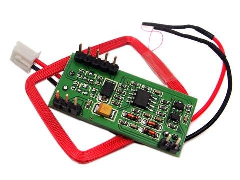
RDM630 -
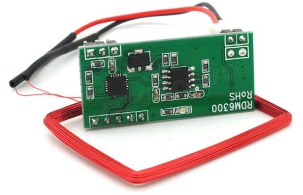
RDM6300

Pin configuration of RDM6300 RFID reader module
The RDM6300 module consists of 10 pins out of which only 5 pins are required to interface this RFID tag reader with Arduino. You can view the pinout below:
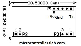
The RDM6300 module consists of three headers as shown above. Details of P1 header pins are given below:
| Pin | Description |
|---|---|
| 1 | This is the TX pin. TX is a data transmit pin of UART of RFID reader |
| 2 | This is the RX pin which is a data receive pin |
| 3 | This pin is not used |
| 4 | This is the GND pin |
| 5 | This is the 5V power supply pin |
The antenna is connected to the P2 header. Details of P2 header pins are given below:
- Pin number one is terminal number one of Antenna
- Pin number two is terminal two of Antenna.
Pin number one on header P3 is a light emitting diode. It is a status or indication LED. It normally remains on and turns off while reading the RFID tag or card.
Below you can view each individual pin in a clear manner:
Working
RDM6300 RFID reader module consists of a driver and coils which are connected to the driver. It generates and modulates radio frequency signal of frequency 125KHz. When we place the 125KHz RFID card near to this generated radio frequency field, they get the energy to transfer power to master the RFID module.
This RDM6300 RFID module is similar to the EM-18 reader module. Because both work on the same radio frequency that is 125KHz and provide a UART serial interface.
For more details on RFID and its working, you can visit this link.
Interfacing RDM6300 with Arduino
We will require the following components for this project.
Required Components:
- Arduino
- RDM6300 or RDM630
- 125 kHz tags or cards (should be EM4100 compatible)
- Connecting Wires
Point to Note: The connection diagram and the Arduino code will work for both RDM6300 and RDM630 modules as they have similar pin configurations and work on the same frequency. We will use RDM6300 for our project.
Assemble the devices as shown in the schematic diagram below:
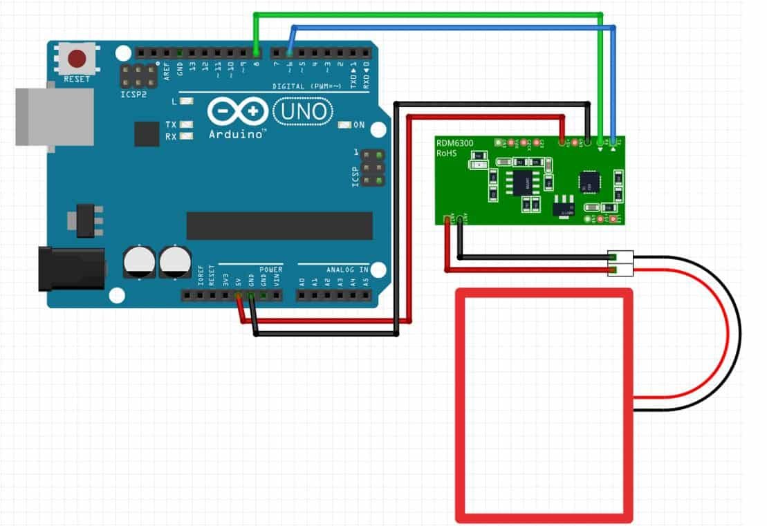
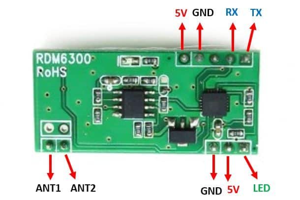
We will connect 4 pins of the RDM6300 module with Arduino. These include the VCC, GND, TX, and RX pins present on Header 1. The VCC will be connected with a 5V pin from the Arduino. GND of both the devices will be in common. We will connect the TX pin with GPIO6 and RX pin with GPIO8 of the Arduino board. The antenna already comes attached to pins ANT1 and ANT2.

Arduino Sketch: RDM6300/RDM630 reading RFID tags/cards
Open your Arduino IDE and go to File > New. A new file will open. Copy the code given below in that file and save it.
#include <SoftwareSerial.h>

const int BUFFER_SIZE = 14;
const int DATA_SIZE = 10;
const int DATA_VERSION_SIZE = 2;
const int DATA_TAG_SIZE = 8;
const int CHECKSUM_SIZE = 2;

SoftwareSerial ssrfid = SoftwareSerial(6,8);

uint8_t buffer[BUFFER_SIZE];
int buffer_index = 0;

void setup() {
 Serial.begin(9600);

 ssrfid.begin(9600);
 ssrfid.listen();

 Serial.println("Initialization Done!");
}

void loop() {
  if (ssrfid.available() > 0){
    bool call_extract_tag = false;

    int ssvalue = ssrfid.read();
    if (ssvalue == -1) {
      return;
    }

    if (ssvalue == 2) {
      buffer_index = 0;
    } else if (ssvalue == 3) {
      call_extract_tag = true;
    }

    if (buffer_index >= BUFFER_SIZE) {
      Serial.println("Error: Buffer overflow detected! ");
      return;
    }

    buffer[buffer_index++] = ssvalue;

    if (call_extract_tag == true) {
      if (buffer_index == BUFFER_SIZE) {
        unsigned tag = extract_tag();
      } else {
        buffer_index = 0;
        return;
      }
    }
  }
}

unsigned extract_tag() {
    uint8_t msg_head = buffer[0];
    uint8_t *msg_data = buffer + 1;
    uint8_t *msg_data_version = msg_data;
    uint8_t *msg_data_tag = msg_data + 2;
    uint8_t *msg_checksum = buffer + 11;
    uint8_t msg_tail = buffer[13];
    Serial.println("--------");
    Serial.print("Message-Head: ");
    Serial.println(msg_head);

    Serial.println("Message-Data (HEX): ");
    for (int i = 0; i < DATA_VERSION_SIZE; ++i) {
      Serial.print(char(msg_data_version[i]));
    }
    Serial.println(" (version)");
    for (int i = 0; i < DATA_TAG_SIZE; ++i) {
      Serial.print(char(msg_data_tag[i]));
    }
    Serial.println(" (tag)");

    Serial.print("Message-Checksum (HEX): ");
    for (int i = 0; i < CHECKSUM_SIZE; ++i) {
      Serial.print(char(msg_checksum[i]));
    }
    Serial.println("");

    Serial.print("Message-Tail: ");
    Serial.println(msg_tail);

    Serial.println("--");

    long tag = hexstr_to_value(msg_data_tag, DATA_TAG_SIZE);
    Serial.print("Extracted Tag: ");
    Serial.println(tag);

    long checksum = 0;
    for (int i = 0; i < DATA_SIZE; i+= CHECKSUM_SIZE) {
      long val = hexstr_to_value(msg_data + i, CHECKSUM_SIZE);
      checksum ^= val;
    }
    Serial.print("Extracted Checksum (HEX): ");
    Serial.print(checksum, HEX);
    if (checksum == hexstr_to_value(msg_checksum, CHECKSUM_SIZE)) {
      Serial.print(" (OK)");
    } else {
      Serial.print(" (NOT OK)");
    }

    Serial.println("");
    Serial.println("--------");

    return tag;

}
long hexstr_to_value(char *str, unsigned int length) {
  char* copy = malloc((sizeof(char) * length) + 1);
  memcpy(copy, str, sizeof(char) * length);
  copy[length] = '\0';
  long value = strtol(copy, NULL, 16);
  free(copy);
  return value;
}
To detect an RFID tag, the RDM6300 module will send a frame of 14 bytes so we will set the Buffer size to 14. This includes head of 1 byte, data of 10 bytes, checksum of 2 bytes and tail of 1 byte.
const int BUFFER_SIZE = 14;
const int DATA_SIZE = 10;
const int DATA_VERSION_SIZE = 2;
const int DATA_TAG_SIZE = 8;
const int CHECKSUM_SIZE = 2;
We will use software serial to communicate between the two devices.
#include <SoftwareSerial.h>Then we will set up the RX and TX pins. These will be passed as a parameter inside the SoftwareSerial().
SoftwareSerial ssrfid = SoftwareSerial(6,8); Demonstration
To see the demonstration of the above code, upload the code to Arduino.
Before uploading code, make sure to select the Arduino board from Tools > Board and also select the correct COM port to which the Arduino board is connected from Tools > Port.

Once the code is uploaded to Arduino, open the serial monitor and set the baud rate to 9600. Press the RST button on the Arduino.
Bring the RFID tag or card close to the antenna. The serial monitor will display the information regarding it. Here you will be able to view the special ID of the tag and its related data. Here we have identified two different tags using this sketch.

You may like to read: